Rotating Room
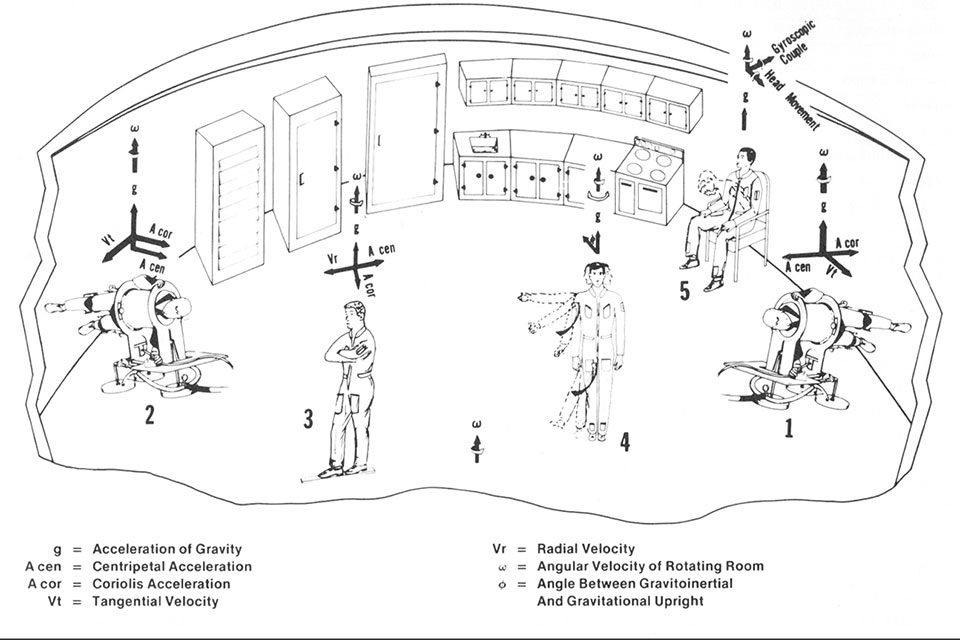
Figure 102. Responses to the force environment in a rotating room. Crewmen 1 and 2, in articulated molds supported by air-bearing devices, are ''walking on the wall'', simulating the orientation in a rotation spacecraft. Crewman 2, walking in the direction of rotation, becomes somewhat heavier because his angular velocity, hence centripetal acceleration, is increased and sums with the Coriolis accelerations generated. Crewman 1, walking opposite to the direction of the rotation, becomes somewhat lighter because his centripetal accelerations are decreased and the Coriolis accelerations must be subtracted. Crewman 3, walking toward the periphery of the room, is exposed to increasing levels of centripetal acceleration and constant levels of Coriolis accelerations. Crewman 4, standing, is demonstrating two phenomena: first, as he moves his arm or leg sideways, a tendency to veer backward, the so-called ''giant-hand'' nucleus. Within each of these projections there is a somatotopic localization.
The rotating room facility of the Ashton Graybiel Spatial Orientation Laboratory at Brandeis University was designed for studying the influence of unusual force environments on human sensory-motor control and orientation.
This facility was designed, fabricated, and assembled at Brandeis University to aid in the study of human behavioral and physiological responses to greater than 1g force environments, of adaptation to unusual forces, and of transitions between force levels. It is the only facility in the United States, the first facility (now decommissioned) was constructed under the direction of Dr. Ashton Graybiel at the Naval Aerospace Medical Institute in Pensacola, Fla.
The rotating room facility is 22 feet in diameter, fully enclosed, with a ceiling height of between 7 feet, 10 inches at the center of rotation and 7 feet 3 inches at the periphery. It has a net weight in excess of 7 tons, and can carry a 6,000 pound payload while producing a gravitoinertial resultant in excess of 4g at the periphery. The room has two separate drive systems. The linear induction motor system was designed specifically for our rotation application. It can accelerate the room to 35 RPM at up to 15o/sec2. The belt drive system can also operate the room over the entire 0 to 35 RPM speed range, but with a maximum acceleration rate of 4o/sec2. The belt system is used during experiments requiring minimum noise and vibration levels, or experiments requiring constant velocity over long durations. It provides the capability of running the room continuously for periods of days or even weeks. If such long runs are desired, cooking, sleeping, and sanitation facilities can be installed in the room with additional funding.
The controller for both drive systems consists of a dedicated industrial computer running multitasking software that controls room position, speed, and acceleration through feedback hardware, and also monitors many safety and operational parameters of the rotating room, while providing this information to personnel in an external control room. The software will shut down the room if certain parameters exceed pre-set limits. The feedback hardware includes a 12 bit absolute optical position encoder and a tachometer which are used to monitor the room's speed and position and to provide closed loop control. Additional sensors also detect safety conditions such as improper door securement. The motion of the room can be controlled by an onboard computer via an RS232 data link carried through slip rings. This is necessary when one computer must control both the onboard experiment and the motion of the room, or when the motion of the room must be contingent on the subject's responses.
The dedicated computer can control room motion with previously programmed motion profiles, motion profiles generated on-the-fly by an onboard computer, or immediate commands from personnel in the external control room. It can accurately control room speed in either direction over the entire 0 to 35 RPM speed range in increments as small as 0.1o/sec. Feedback control ensures a constant room speed while people or objects are moving within the room. Acceleration rates of up to 15o/sec2 can be achieved; constant velocity can be maintained to within +/- .001% at low speeds and 0.1% at the highest speed. The room can also be sinusoidally oscillated over a wide range of frequencies. Over the entire speed range z-axis vibration has been measured at <.001g.
The computer control of the rotating room is monitored by a trained operator in the control room, who also monitors the onboard experiments through onboard video cameras and microphones. The operator has redundant two way communication with the onboard experimenter, and can take over manual control of the slow rotation room, and apply emergency electric braking (independent of the two drive systems and of building power) if necessary.
Rotating Room Floor Plan
 Room diameter= 20' 10"
- Door width= 45.5"
- Door height= 77.5"
- Floor to ceiling height:
- (at walls)= 88.7"
- (center)= 94"